Tekla Structures isn’t just BIM software; it’s your secret weapon for conquering complex construction projects. Think of it as the ultimate digital toolbox, packed with features that let you model, design, and collaborate like a pro. From initial sketches to final fabrication drawings, Tekla Structures streamlines the entire process, saving you time and headaches along the way. Get ready to dive into a world where building information modeling becomes intuitive and even, dare we say, fun.
This guide explores the core functionalities of Tekla Structures, from basic modeling techniques to advanced features like clash detection and quantity takeoff. We’ll cover everything from creating simple building models to managing complex projects with multiple users, all while emphasizing best practices for efficiency and collaboration. We’ll also compare Tekla Structures to other BIM software and delve into its integration with structural analysis tools, data management capabilities, and customization options.
Prepare to become a Tekla Structures ninja!
Tekla Structures Introduction
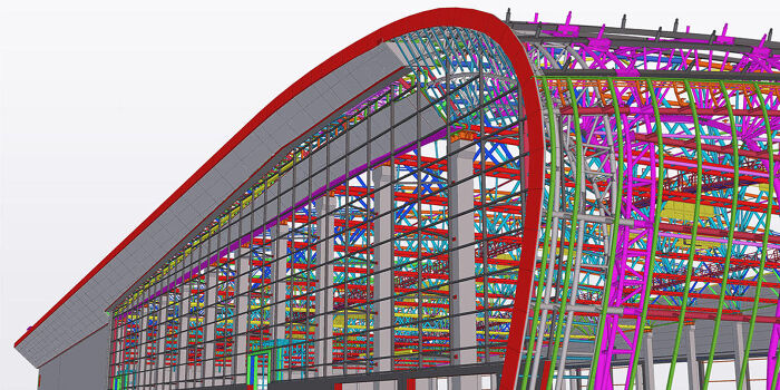
Tekla Structures is a powerful Building Information Modeling (BIM) software used extensively in the construction industry for structural design and detailing. It’s known for its ability to create accurate and detailed 3D models, facilitating efficient collaboration among project stakeholders and streamlining the entire building process from design to fabrication. Its strengths lie in its comprehensive features, robust modeling capabilities, and seamless integration with other industry software.Tekla Structures’ core functionality revolves around creating, modifying, and analyzing 3D models of structures.
This involves defining geometry, assigning materials, adding connections, and generating fabrication drawings. The software allows for detailed modeling of various structural elements, including beams, columns, slabs, walls, and foundations, with options for advanced analysis and design checks. Its parametric modeling capabilities enable quick design iterations and efficient modification of existing models. Furthermore, it provides tools for clash detection, quantity takeoff, and project management, all crucial aspects of modern construction.
Tekla Structures Modules
Tekla Structures is comprised of several integrated modules, each contributing to a specific aspect of the building process. These modules work together to provide a comprehensive BIM solution. While the specific modules available may vary depending on the license, common examples include modules focused on modeling, detailing, fabrication, and analysis. For instance, the detailing module allows users to generate detailed shop drawings for fabrication, including dimensions, annotations, and material specifications.
The analysis module integrates with other analysis software to allow for structural verification and optimization. The overall modular design allows users to customize their workflow and utilize only the necessary functionalities for a given project.
Tekla Structures vs. Other BIM Software
Tekla Structures occupies a unique niche within the BIM software landscape. While other BIM software like Revit and ArchiCAD offer strong architectural and general building modeling capabilities, Tekla Structures is specifically geared towards structural engineering and detailing. Revit, for example, excels in architectural design and coordination, but may lack the level of detail and specialized tools offered by Tekla Structures for structural elements.
Similarly, ArchiCAD focuses on architectural design and visualization. The key differentiator is Tekla Structures’ strength in generating fabrication-ready drawings and its extensive library of structural components. This makes it particularly suitable for projects involving prefabrication and off-site construction. A comparison might highlight Revit’s superior architectural capabilities against Tekla Structures’ superior structural detailing and fabrication capabilities; the choice depends heavily on the project’s specific needs and the team’s expertise.
For example, a project with significant prefabricated components would likely benefit from Tekla Structures’ precise detailing and fabrication features, whereas a project focused heavily on architectural design might find Revit a more efficient choice.
Modeling Techniques in Tekla Structures
Tekla Structures offers a powerful and versatile environment for building information modeling (BIM). Mastering its modeling techniques is key to creating efficient and accurate structural models. This section will cover fundamental and advanced techniques, guiding you through the process of building a simple model and progressing to more complex scenarios.
Let’s start with the basics. Building a simple model in Tekla Structures typically involves defining the project units, creating the building’s geometry using basic shapes like beams, columns, and slabs, and then adding details like connections and reinforcement. The software’s intuitive interface allows for quick model creation, but understanding the underlying principles will greatly enhance efficiency.
Creating a Simple Building Model
To create a simple building model, begin by setting up the project units (e.g., meters). Then, you’d typically start with the foundation, perhaps using a concrete slab defined by its dimensions and thickness. Next, you would create columns, usually rectangular or circular profiles, placing them according to the architectural plan. Beams are added next, connecting the columns and supporting the roof.
Finally, you’d model the roof slab, mirroring the foundation’s process. Throughout this process, Tekla Structures allows for easy modification and adjustment of element dimensions and positions. The process is iterative; you’ll likely refine the model as you add more details.
Best Practices for Efficient Model Creation
Efficient model creation hinges on planning and organization. Before starting, a clear understanding of the project’s requirements is essential. This includes accurate architectural and structural drawings. Adopting a systematic approach—starting with the main structural elements and progressively adding details—is crucial. Using the software’s snapping tools and alignment features will ensure precision and minimize errors.
Regularly saving your work prevents potential data loss. Furthermore, leveraging Tekla Structures’ built-in features, such as automatic numbering and reporting tools, streamlines the workflow and reduces manual effort.
Advanced Modeling Techniques: Components and Families
Tekla Structures’ power lies in its ability to manage complex projects using components and families. Components are pre-defined elements, such as standard steel sections or precast concrete panels, that can be easily inserted into the model. Families, on the other hand, allow you to create custom components with parameters that can be adjusted, enabling the creation of numerous variations from a single definition.
For instance, a family might define a steel beam with adjustable length, width, and height. Using components and families drastically reduces modeling time and ensures consistency across the project.
Modeling a Complex Structural Element: Step-by-Step Guide
Let’s model a complex element, say, a steel staircase. First, define the staircase’s geometry, including the number of steps, rise, and run. Then, create individual steps using Tekla Structures’ drawing tools. These steps would likely be modeled as plates or custom components. Next, you’d add stringers, supporting the steps.
Stringers might be modeled as beams or complex shapes created using the software’s advanced modeling tools. Finally, add any necessary railings or handrails. Throughout this process, you’d utilize Tekla Structures’ features for creating connections between the steps and stringers, ensuring structural integrity. This detailed approach, while time-consuming for a single staircase, becomes incredibly efficient when repeated for multiple similar elements within a larger project.
Using families, you could create a staircase family to streamline the process even further.
Tekla Structures and Collaboration
So, you’ve got your Tekla model humming along, but now you need to bring in the team. Collaboration in Tekla Structures isn’t just about sharing files; it’s about a smooth, efficient workflow that keeps everyone on the same page and avoids those dreaded model conflicts. This section dives into the nuts and bolts of effective teamwork in Tekla.Collaboration in Tekla Structures hinges on effective communication and the use of its built-in tools to manage a shared model.
Different methods exist depending on project size, team structure, and the level of detail required for collaboration. A well-defined workflow is key to preventing chaos and ensuring everyone is working with the most up-to-date version of the model.
Methods for Collaborating on a Tekla Structures Project
Multiple users can collaborate on a Tekla Structures project using several methods, each with its own advantages and disadvantages. Choosing the right method depends on project size, team size, and the complexity of the design.
- Using a Network Shared Drive: This is a straightforward approach where the Tekla model is saved on a shared network drive accessible to all collaborators. While simple to set up, this method can lead to version control issues and model corruption if not managed carefully. Regular backups and clear communication protocols are crucial.
- Utilizing Tekla Model Sharing: Tekla Model Sharing is a more robust solution, designed to handle concurrent access to a model. Users can work on different parts of the model simultaneously, minimizing conflicts. It provides version control and allows for tracking changes made by each user. This is generally the preferred method for larger projects.
- Employing a BIM Collaboration Platform: Platforms like BIM 360 or other cloud-based solutions provide a central repository for the Tekla model and other project data. These platforms often integrate with Tekla Structures, offering advanced version control, clash detection, and issue tracking capabilities. This method offers the highest level of control and collaboration, but it requires a subscription to the chosen platform.
Workflow for Managing Revisions and Updates
A well-defined workflow is critical for managing revisions and updates in a shared Tekla model. This workflow should clearly Artikel how changes are made, reviewed, and approved.
- Establish a clear naming convention for model versions. This could be based on dates, revision numbers, or a combination of both (e.g., ProjectName_RevA_20240308).
- Implement a change request system. All changes should be formally requested and approved before implementation. This ensures that changes are well-considered and don’t introduce conflicts.
- Regular backups are essential. Frequent backups minimize the risk of data loss and allow for easy rollback to previous versions if necessary.
- Utilize Tekla Structures’ version control features. These features allow for tracking changes, comparing different versions, and reverting to earlier states if required.
- Conduct regular model checks. Regular checks help identify and resolve potential conflicts or errors before they become major issues. This can involve using Tekla Structures’ built-in clash detection tools.
Tools Within Tekla Structures that Facilitate Collaboration
Tekla Structures offers several tools specifically designed to streamline collaboration.
- Model Sharing: As mentioned earlier, Tekla Model Sharing allows multiple users to work on the same model concurrently, reducing conflicts and improving efficiency.
- Version Control: Tekla Structures’ version control system tracks changes, allowing users to compare different versions and revert to previous states if needed. This helps maintain a clear history of modifications.
- Clash Detection: This tool helps identify potential conflicts between different parts of the model, ensuring a coordinated design.
- Issue Tracking: Within the model, users can flag and track issues, making it easier to manage and resolve problems collaboratively. This often integrates with external issue tracking software.
- Collaboration Tools (e.g., annotations, markups): These allow users to communicate directly within the model, providing feedback and clarifying design intentions. For example, a team member can annotate a specific area needing revision, ensuring clear communication.
Data Management in Tekla Structures
Keeping your Tekla Structures projects organized and your data readily accessible is crucial for efficiency and collaboration. Effective data management ensures you can easily find what you need, track changes, and avoid costly errors. This section will cover strategies for organizing your model data and utilizing Tekla Structures’ export capabilities for analysis and reporting.
Organizing your model data effectively within Tekla Structures involves a multi-pronged approach. Firstly, a clear and consistent naming convention for your models, components, and files is essential. Think of it like a well-organized library – you wouldn’t want to search through haphazardly named books! Secondly, utilizing Tekla Structures’ built-in tools for organizing objects within the model, such as using attributes and classifications, is key.
Finally, regularly backing up your work to prevent data loss is paramount. This can be done using Tekla Structures’ built-in backup functionality or through external backup solutions.
Data Export Options
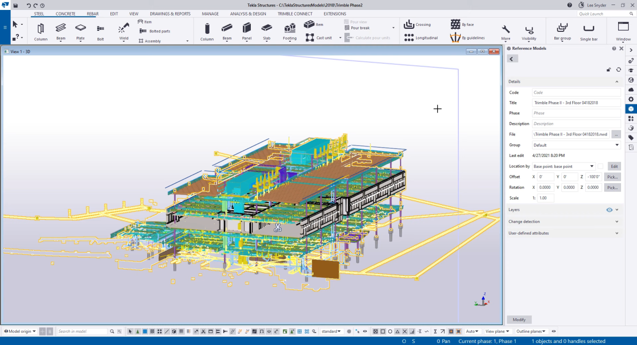
Tekla Structures offers a variety of data export options, allowing you to share information with other software and stakeholders. These options are crucial for collaboration and analysis. The choice of export format depends on the intended use of the exported data.
For example, exporting to IFC (Industry Foundation Classes) allows for interoperability with other Building Information Modeling (BIM) software. This is incredibly useful for collaborating with architects, MEP engineers, and other disciplines on a project. Exporting to DWG (Drawing Exchange Format) is useful for sharing 2D drawings with contractors and clients who may not have access to Tekla Structures.
Other formats, such as DXF, allow for the transfer of geometry to CAD programs. Tekla Structures also allows for exporting to various analysis formats, which will be discussed further below.
Using Tekla Structures Data for Analysis and Reporting
The data generated within Tekla Structures isn’t just for visualization; it’s a rich source of information for analysis and reporting. This data can be leveraged to optimize designs, track progress, and generate comprehensive reports.
For instance, you can extract quantities of materials directly from the model, generating detailed material takeoffs for accurate cost estimations. This avoids manual counting and reduces the potential for errors. Furthermore, you can use the model data to perform structural analysis by exporting the model to analysis software such as Robot Structural Analysis or other FEA packages. The results from these analyses can then be imported back into Tekla Structures to inform design modifications and optimize the structural performance of the model.
Finally, Tekla Structures can generate reports on various aspects of the project, including material quantities, clash detection results, and other key metrics. These reports can be customized to meet specific project requirements and can be used to communicate progress and information to stakeholders.
Analysis and Design using Tekla Structures
Tekla Structures isn’t just about building a pretty 3D model; it’s a powerful tool for integrating analysis and design directly into the workflow. This allows for a seamless transition from conceptual design to detailed engineering, reducing errors and saving valuable time. By connecting with various analysis programs, you can leverage the power of finite element analysis (FEA) and other methods to verify the structural integrity of your designs, all within the familiar Tekla environment.This section explores the integration capabilities of Tekla Structures, demonstrating how to efficiently generate reports and drawings, and highlighting best practices for using the software in structural design verification.
We’ll delve into practical applications and demonstrate how this integrated approach streamlines the design process.
Tekla Structures Integration with Structural Analysis Software
Tekla Structures boasts robust interoperability with a wide range of structural analysis software packages. This seamless data exchange allows for efficient workflows. For instance, you can export the Tekla model to a program like Robot Structural Analysis or SAP2000 for analysis. The analysis results, including stresses, deflections, and support reactions, are then imported back into Tekla Structures.
This closed-loop process enables designers to quickly assess the structural performance of their designs and make necessary modifications directly within the modeling environment. The process typically involves exporting the model in a neutral format like IFC or a program-specific format, performing the analysis, and then importing the results back into Tekla, often through custom scripts or add-ins to automate the process.
Generating Reports and Drawings from Tekla Structures Model Data
Tekla Structures provides comprehensive tools for generating detailed reports and drawings directly from the model. This eliminates the need for manual data entry and minimizes the risk of errors. The software allows for the creation of various reports, including material takeoffs, fabrication drawings, and shop drawings. These reports can be customized to meet specific project requirements, including adding company logos and project-specific information.
Similarly, drawings can be generated automatically, with features like automated dimensioning, labeling, and section views significantly reducing drafting time. For example, a user can generate a report detailing the quantity of steel needed for a project, or create detailed shop drawings for individual steel members, complete with dimensions and connection details.
Best Practices for Utilizing Tekla Structures for Structural Design Verification
Effective use of Tekla Structures for design verification requires a structured approach. It’s crucial to establish a clear workflow that incorporates analysis results directly into the design process. This iterative process involves modeling, analysis, result review, and model refinement. Regular checks and comparisons between the analytical results and design assumptions are essential. Furthermore, utilizing Tekla Structures’ built-in tools for clash detection and model checking helps identify potential design conflicts early in the process.
Implementing quality control measures, such as peer reviews and independent checks of critical design aspects, further enhances the reliability of the structural design. A robust quality assurance plan, integrated with the design process, helps ensure the structural integrity of the final design. For example, a designer might use Tekla Structures’ clash detection tools to identify conflicts between different structural elements before fabrication, preventing costly rework later.
Customization and Extensions in Tekla Structures
Tekla Structures, while incredibly powerful out-of-the-box, truly shines when tailored to your specific needs. Customization and extensions allow you to streamline workflows, automate repetitive tasks, and integrate with other software, ultimately boosting efficiency and productivity. This section explores the various ways you can personalize your Tekla Structures experience.
The ability to customize Tekla Structures is a key factor in its widespread adoption across various industries. From small architectural firms to massive construction companies, the flexibility to adapt the software to specific project requirements and company standards is invaluable. This is achieved through a combination of built-in customization options and the development and implementation of custom extensions.
Customizing Tekla Structures Workflows
Tekla Structures offers several built-in tools for workflow customization. These include the ability to modify existing macros, create custom attributes for objects, and adjust settings within the user interface. For example, you can create a macro to automate the process of adding specific dimensions to a drawing, or modify an existing macro to suit your preferred annotation style.
Custom attributes can be added to beams, columns, or other elements to store and manage project-specific data. Modifying the user interface allows for a personalized experience, optimizing the placement of toolbars and shortcuts for individual users or teams. The extent of these customizations is largely limited only by the user’s technical skills and understanding of the software’s inner workings.
Developing and Implementing Custom Extensions
Creating custom extensions requires programming skills, typically using the Tekla Structures API (Application Programming Interface). The API provides a set of tools and functions that allow developers to interact with Tekla Structures, creating new functionalities or modifying existing ones. This involves writing code in languages such as C# or Visual Basic .NET to create custom components, commands, and dialog boxes.
Once developed, extensions are packaged and deployed within the Tekla Structures environment, making the new functionality readily available to users. For example, an extension could be developed to automatically generate shop drawings based on specific criteria, or to integrate Tekla Structures with a project management software. The complexity of these extensions can range from simple scripts to large-scale applications.
Available Third-Party Extensions
Many third-party developers create and offer extensions that enhance Tekla Structures’ capabilities. These extensions often address specific industry needs or provide functionalities not included in the base software. They are typically available for purchase or download from online marketplaces or directly from the developers. These extensions can cover a wide range of applications, from improved visualization and rendering to specialized tools for specific construction tasks.
For instance, some extensions might offer advanced clash detection capabilities, while others might streamline the process of creating detailed cost estimations directly within Tekla Structures. Care should be taken to evaluate the reliability and compatibility of any third-party extension before implementation.
Advanced Features of Tekla Structures

Tekla Structures offers a suite of advanced features that significantly boost efficiency and accuracy in structural design and detailing. These tools move beyond basic modeling, enabling streamlined workflows and improved collaboration across the project lifecycle. This section explores some of the most impactful advanced features, focusing on their application and comparative effectiveness.
Clash Detection
Clash detection in Tekla Structures is a powerful tool for identifying and resolving conflicts between different building components before construction begins. This proactive approach prevents costly rework and delays on-site. The software analyzes the 3D model, highlighting areas where elements intersect or are too close for safe installation. Different clash types can be categorized and prioritized, allowing for efficient resolution.
For example, a clash between a ductwork system and a structural beam would be flagged, allowing the designer to adjust the placement of one or both components to avoid interference. The detailed clash reports provide visual representations and measurements of the conflicts, making it easier to understand and resolve them. The ability to filter clashes by discipline (MEP, structural, architectural) allows for focused problem-solving.
Quantity Takeoff
Accurate quantity takeoff is crucial for budgeting and material procurement. Tekla Structures automates this process by extracting precise measurements directly from the 3D model. This eliminates the need for manual calculations, reducing the risk of errors and saving significant time. The software can generate detailed reports including material quantities, lengths, areas, and volumes. For example, a project requiring 1000 linear meters of specific steel sections can have this quantity automatically calculated and reported, reducing manual estimations and potential material shortages.
Further, integration with other project management software can streamline the process of ordering materials based on the generated quantities.
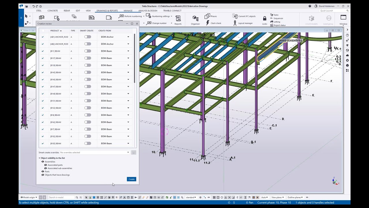
Fabrication Detailing
Tekla Structures’ fabrication detailing capabilities are highly valuable for prefabrication workflows. The software automatically generates detailed fabrication drawings, including shop drawings, cutting lists, and assembly instructions. These drawings are precise and consistent, minimizing errors and improving communication between the design team and the fabricators. This reduces the need for manual drafting, speeds up the fabrication process, and enhances the overall quality of the final product.
For instance, a complex steel connection can be modeled in Tekla Structures, and the software will automatically generate detailed drawings showing all dimensions, bolt locations, and welding specifications. This detailed level of information eliminates ambiguity and ensures accurate fabrication.
Advanced Feature Efficiency Comparison
The efficiency of Tekla Structures’ advanced features varies depending on the project’s scale and complexity. For instance, clash detection is most beneficial in large, complex projects with numerous disciplines involved. Quantity takeoff is crucial for all projects, regardless of size, but the time saved is more significant on larger projects. Fabrication detailing is especially valuable in prefabrication-heavy projects, significantly reducing the time and cost associated with traditional manual detailing.
A small residential project might primarily benefit from quantity takeoff, while a large stadium construction project would see significant gains from all three features, particularly clash detection. The overall efficiency increase is a function of the project’s characteristics and the features utilized.
Troubleshooting and Best Practices
Tekla Structures, while powerful, can sometimes present challenges. Understanding common issues and implementing best practices significantly improves workflow efficiency and data integrity, ultimately leading to smoother project delivery. This section covers common problems, their solutions, and strategies for optimizing performance and maintaining data quality.
Common Tekla Structures Issues and Solutions
Many problems stem from model organization, clash detection, and data management. For instance, slow performance often results from overly complex models or insufficient system resources. Similarly, data inconsistencies can lead to errors during analysis or fabrication.
- Issue: Model slowdowns and freezes. Solution: Regularly purge unused objects, optimize model geometry (avoid excessive detail where unnecessary), and ensure sufficient RAM and processing power. Consider upgrading your hardware or optimizing your Tekla Structures settings (e.g., graphics card settings, model simplification).
- Issue: Clash detection issues. Solution: Employ a systematic clash detection workflow, regularly checking for clashes between different disciplines. Use clear naming conventions for components to facilitate identification and resolution of clashes.
- Issue: Data inconsistencies. Solution: Implement a robust data management strategy using Tekla Model Sharing or other collaborative platforms. Maintain a consistent naming convention and utilize attributes effectively for easy identification and filtering of elements.
- Issue: Difficulty in finding specific objects in a large model. Solution: Employ effective naming conventions and utilize Tekla Structures’ powerful search and filtering tools. Consider using object selection filters and creating views to isolate specific parts of the model.
Optimizing Tekla Structures Performance
Optimizing performance hinges on proactive model management and efficient hardware utilization. A well-organized model is significantly faster and more manageable than a cluttered one.
- Model Simplification: Avoid unnecessary detail in areas not requiring high precision. Use simplified geometry where appropriate. For instance, using simple blocks instead of highly detailed components for far-away objects.
- Regular Purging: Periodically purge unused objects and components. This significantly reduces file size and improves performance.
- Hardware Optimization: Ensure sufficient RAM, a fast processor, and a dedicated graphics card for optimal performance. Consider using Solid State Drives (SSDs) for faster loading times.
- Tekla Structures Settings: Adjust Tekla Structures settings to match your hardware capabilities and project requirements. Experiment with different graphic settings to find the optimal balance between visual quality and performance.
Data Integrity Checklist
Maintaining data integrity is crucial for accurate analysis, fabrication, and construction. This checklist Artikels key steps to ensure your Tekla Structures projects remain reliable and error-free.
- Consistent Naming Conventions: Implement a standardized naming convention for all objects and components throughout the project.
- Regular Backups: Regularly back up your models to prevent data loss due to unforeseen circumstances.
- Version Control: Utilize version control systems to track changes and revert to previous versions if necessary.
- Attribute Management: Use attributes consistently and effectively to track important information about components.
- Data Validation: Regularly validate your data to identify and correct inconsistencies before they cause problems.
- Collaboration Protocols: Establish clear collaboration protocols for teams working on the same model to avoid conflicts and data inconsistencies.
Real-world Applications of Tekla Structures
Tekla Structures isn’t just software; it’s a powerful tool transforming how we design and build structures worldwide. Its versatility extends across various construction sectors, impacting project timelines, budgets, and overall quality. From skyscrapers to stadiums, its application consistently demonstrates enhanced efficiency and precision.
The software’s impact is felt across numerous project types, leveraging its BIM capabilities to streamline processes and improve collaboration. Its use isn’t limited to specific building types; rather, it’s adaptable to the unique demands of diverse projects, proving its worth in both simple and complex scenarios.
Tekla Structures in Different Construction Projects
Tekla Structures finds application in a broad range of construction projects. Its ability to handle complex geometries and large datasets makes it ideal for high-rise buildings, where intricate detailing and coordination are crucial. In industrial construction, its strength lies in managing the fabrication and assembly of massive steel structures, ensuring precise fit and minimizing on-site errors. Infrastructure projects, such as bridges and tunnels, benefit from Tekla’s ability to model complex curves and intersections, facilitating accurate quantity takeoffs and efficient construction planning.
Even smaller-scale projects, like residential buildings, can leverage Tekla’s user-friendly interface and powerful modeling tools for improved design and construction management.
Case Study: Stadium Construction with Tekla Structures
A recent stadium project in [Fictional City, State] showcased the transformative potential of Tekla Structures. The project, encompassing over 70,000 seats, complex roofing systems, and intricate internal spaces, initially faced challenges with traditional 2D drafting methods. The team switched to Tekla Structures, utilizing its advanced modeling capabilities to create a precise 3D model encompassing all aspects of the design.
This allowed for early clash detection, identifying and resolving potential conflicts between different trades before construction commenced. The detailed model facilitated accurate material takeoffs, optimizing material procurement and minimizing waste. Furthermore, the model served as a crucial tool for on-site construction management, guiding workers and ensuring the project’s timely completion. The result was a successful project delivered on time and within budget, significantly reducing rework and on-site conflicts.
The project’s success highlights Tekla’s capacity to manage even the most complex projects, minimizing risks and enhancing efficiency.
Benefits of Tekla Structures Across Project Phases
The advantages of using Tekla Structures extend throughout all project phases. During the design phase, it facilitates collaborative design review and allows for early clash detection, preventing costly errors later on. In the fabrication phase, the detailed models generated by Tekla Structures provide precise instructions for fabrication, minimizing errors and improving productivity. During the construction phase, the model guides on-site workers, ensuring accurate assembly and minimizing delays.
Finally, during the operation and maintenance phase, the model serves as a valuable asset, providing accurate as-built information for future modifications and repairs. The consistent use of the model throughout the entire project lifecycle significantly improves efficiency and minimizes risks.
Future Trends in Tekla Structures
Tekla Structures, already a powerhouse in BIM for structural engineering, is poised for significant advancements in the coming years. We can expect to see a continued push towards greater automation, improved collaboration tools, and deeper integration with other technologies shaping the AEC industry. This evolution will be driven by the increasing demand for efficiency, accuracy, and sustainable design practices.The future of Tekla Structures will likely be characterized by enhanced AI-driven capabilities and a more seamless integration with the broader digital twin ecosystem.
This will allow for more efficient workflows and improved decision-making throughout the entire project lifecycle.
Increased Automation and AI Integration
Tekla Structures is already incorporating AI to streamline various tasks, but future developments will likely see more sophisticated applications. For example, we might see AI-powered tools that automatically generate optimized designs based on specified parameters, significantly reducing the time and effort required for preliminary design stages. Imagine an AI assistant that suggests optimal beam sizes and connection details based on the building’s load calculations, material properties, and design codes.
This level of automation will free up engineers to focus on more complex and creative aspects of the design process. Further, expect to see more robust clash detection and resolution capabilities driven by AI, minimizing errors and rework during the construction phase.
Enhanced Collaboration and Data Interoperability
Improved collaboration tools are key to the future of Tekla Structures. This means better integration with other BIM software, cloud-based platforms, and project management tools. Imagine a scenario where all project stakeholders – architects, structural engineers, MEP engineers, and contractors – can access and work on the same model simultaneously, in real-time, regardless of their location. This would significantly enhance communication and coordination, reducing conflicts and delays.
Tekla Structures is, like, totally essential for any serious structural engineering project, right? But managing all those projects and client comms can be a nightmare. That’s where something like waveapps could seriously level-up your workflow. Imagine streamlined communication and project tracking – it would free up so much time to focus on actually using Tekla Structures to build amazing things.
Expect smoother data exchange with platforms like Autodesk BIM 360 or similar cloud-based solutions, allowing for a more integrated and efficient workflow.
Expansion of Digital Twin Capabilities
The development of digital twins – virtual representations of physical assets – is rapidly gaining traction. Tekla Structures will likely play a crucial role in this trend, allowing for the creation of highly detailed and accurate digital twins of structures. These digital twins can be used for various purposes, including predictive maintenance, performance monitoring, and lifecycle management. For instance, sensors embedded in a completed structure could feed real-time data into the digital twin, allowing engineers to monitor the structural health and identify potential problems before they become major issues.
This proactive approach could significantly reduce maintenance costs and improve the overall safety and longevity of structures.
Integration with Extended Reality (XR) Technologies
The integration of XR technologies, such as augmented reality (AR) and virtual reality (VR), holds immense potential for transforming the way we design, construct, and manage structures. Imagine architects and engineers using AR headsets to overlay the Tekla model onto the actual construction site, allowing them to visualize the design in its real-world context and identify potential issues early on.
VR could be used for immersive design reviews and training simulations, improving communication and reducing errors. This immersive experience would greatly enhance collaboration and understanding between all stakeholders. The use of XR in conjunction with a digital twin could enable remote collaboration and inspection, even across geographical boundaries.
Sustainable Design and Material Optimization
Future versions of Tekla Structures will likely place a greater emphasis on sustainable design practices. This could involve the integration of tools that help engineers optimize material usage, reduce waste, and select more sustainable building materials. The software could also incorporate features that allow for the assessment of a structure’s environmental impact throughout its lifecycle, enabling more informed decision-making.
For example, the software might provide detailed reports on the embodied carbon of different design options, helping engineers to make more environmentally conscious choices. This would align Tekla Structures with the growing industry focus on reducing carbon emissions in the construction sector.
Last Word
So, there you have it – a whirlwind tour of Tekla Structures! From its powerful modeling capabilities to its collaborative features and advanced analysis tools, Tekla Structures is more than just software; it’s a complete solution for modern construction. Mastering Tekla Structures will not only boost your efficiency and accuracy but also elevate your design thinking. By embracing this powerful tool, you’ll be ready to tackle any project, no matter how challenging.
Now go forth and build amazing things!
FAQ Guide
Is Tekla Structures difficult to learn?
The learning curve depends on your prior BIM experience. While it’s powerful, Tekla Structures offers plenty of tutorials and resources to help you get started. Many users find it intuitive once they grasp the fundamentals.
What kind of hardware do I need to run Tekla Structures?
You’ll need a reasonably powerful computer with a good graphics card, ample RAM, and a solid-state drive (SSD) for optimal performance. Tekla’s website provides detailed system requirements.
Is Tekla Structures compatible with other software?
Yes! Tekla Structures integrates with numerous other software packages, including structural analysis programs, rendering software, and project management tools. The specific compatibilities are detailed in Tekla’s documentation.
What is the cost of Tekla Structures?
Tekla Structures is a licensed software, and pricing varies depending on the license type and features included. Contact Tekla directly for accurate pricing information.
What kind of support is available for Tekla Structures?
Tekla offers various support options, including online documentation, tutorials, and dedicated customer support channels. The level of support depends on your license agreement.