Fusion360 – Fusion 360 is more than just CAD software; it’s a complete design and manufacturing ecosystem. From initial concept sketches to final product manufacturing, Fusion 360 provides a seamless workflow for engineers, designers, and makers of all levels. This guide dives deep into its powerful features, exploring everything from intuitive interface customization to advanced simulation and CAM capabilities. We’ll cover modeling techniques, collaboration strategies, industry-specific applications, and even troubleshooting tips to help you master this versatile tool.
This guide will walk you through the ins and outs of Fusion 360, equipping you with the knowledge to tackle complex projects with confidence. Whether you’re a seasoned professional or just starting your CAD journey, you’ll find valuable insights and practical advice to enhance your design and manufacturing process. Get ready to unlock the full potential of Fusion 360!
Fusion 360 Interface and User Experience
Fusion 360 boasts a pretty intuitive interface, but like any CAD software, it takes some getting used to. This section breaks down the workspace and key features, compares it to other options, and shows you how to customize it for your own workflow. Think of it as your personalized CAD power-up guide.
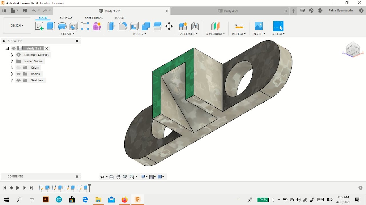
Navigating the Fusion 360 workspace is key to unlocking its potential. The interface is designed around a flexible, customizable environment that adapts to your specific needs and project type. Understanding the core components—the design workspace, the browser, and the various toolbars—is crucial for efficient modeling and design.
Fusion 360 Workspace Overview
The Fusion 360 workspace is organized around a central design area where you create your models. Surrounding this area are various toolbars and panels providing access to different tools and features. The browser, located on the left-hand side, acts as a hierarchical structure displaying all elements within your design, making it easy to select and manipulate individual components. The ribbon at the top provides quick access to common commands and features, while the properties panel (often located on the right) displays and allows modification of selected object properties.
The entire layout can be customized to fit your personal preferences.
Comparison of Fusion 360 with Other CAD Software
Choosing the right CAD software depends on your specific needs and budget. Here’s a quick comparison of Fusion 360 against some popular alternatives. Keep in mind that features and pricing can change, so always check the software vendor’s website for the most up-to-date information.
| Feature | Fusion 360 | SolidWorks | AutoCAD |
|---|---|---|---|
| Cost | Subscription-based, free for hobbyists and students | Perpetual license or subscription | Perpetual license or subscription |
| Ease of Use | Relatively easy to learn, intuitive interface | Steeper learning curve, powerful features | Steeper learning curve, powerful features, command-line focused |
| 3D Modeling Capabilities | Parametric and direct modeling capabilities | Primarily parametric modeling | Primarily 2D drafting, but with 3D modeling capabilities |
| CAM Capabilities | Integrated CAM features | Requires separate CAM software or add-on | Requires separate CAM software |
Customizing the Fusion 360 Interface
Optimizing your Fusion 360 workflow involves tailoring the interface to your specific needs and preferences. This includes adjusting toolbars, workspaces, and shortcuts. A well-organized interface can significantly improve efficiency and reduce frustration.
You can customize toolbars by right-clicking on them and selecting the tools you want to add or remove. You can also create custom toolbars to group related tools together. Workspaces can be switched to optimize the layout for specific tasks, like sculpting or CAM. Creating custom keyboard shortcuts for frequently used commands can dramatically speed up your workflow.
Experiment and find what works best for you—it’s all about finding that sweet spot of efficiency and comfort.
Fusion 360 Modeling Techniques
Fusion 360 offers a powerful and versatile suite of modeling tools, allowing users to create incredibly detailed and complex 3D models. Its parametric nature means changes to one part of the design automatically update related features, streamlining the design process and reducing errors. This section explores the core modeling techniques and provides a practical example.
Fusion 360 primarily employs a parametric modeling approach, meaning that every design element is defined by parameters (like dimensions, constraints, and relationships). This allows for iterative design and easy modification. It supports several core modeling techniques, each useful for different design scenarios.
Subtractive Modeling
Subtractive modeling, also known as subtractive manufacturing, simulates the process of removing material from a solid block to create the desired shape. Think of it like carving a sculpture from a block of wood. In Fusion 360, this is achieved using features like Extrude Cut, Revolve Cut, and Pocket. For instance, to create a hole in a block, you’d use the Extrude Cut feature, defining the hole’s diameter and depth.
Similarly, a complex shape can be carved out by combining multiple cut features. This approach is particularly well-suited for designs requiring precise internal geometries or intricate details.
Additive Modeling
Additive modeling, in contrast, builds up the model by adding material layer upon layer. This mirrors processes like 3D printing. In Fusion 360, features like Extrude, Revolve, and Combine are used to add material. To create a simple cylinder, you’d use the Revolve feature, defining the profile and angle of revolution. More complex shapes are built by combining multiple additive features.
This is ideal for creating organic shapes or complex assemblies.
Freeform Modeling
Freeform modeling offers a more intuitive and less constrained approach to design, allowing for organic shapes and complex curves. While Fusion 360 doesn’t have dedicated freeform sculpting tools like some other software packages, you can achieve similar results by combining several features, like using multiple lofts or sweeps to create smooth, flowing surfaces. This approach is well-suited for creating designs that don’t lend themselves easily to traditional parametric modeling.
Creating a Complex 3D Model: A Step-by-Step Guide
Let’s create a simple gear using Fusion 360’s parametric modeling capabilities.
- Create a Base: Start by creating a cylindrical base using the Revolve feature. Define the diameter and height of the cylinder.
- Add Teeth: Use the Circular Pattern feature to create multiple copies of a single tooth profile. The tooth profile itself can be created using the Extrude feature. You’ll need to precisely define the tooth’s height, width, and spacing to achieve a functional gear.
- Refine the Geometry: Use the Fillet feature to round off sharp edges and corners for a more aesthetically pleasing and structurally sound gear. You can adjust the fillet radius to control the smoothness of the curves.
- Add a Central Hole: Use the Extrude Cut feature to create a cylindrical hole in the center of the gear, allowing for mounting on a shaft.
- Create Components: For a more complex design, consider breaking the gear down into multiple components. For instance, you might create separate components for the gear body and the teeth, allowing for greater design flexibility and easier modification.
Advanced Modeling Techniques: Components and Patterns
Components in Fusion 360 allow you to create sub-assemblies within a larger design. This is particularly useful for managing complexity and promoting reusability. Imagine designing a chair: you could create separate components for the legs, seat, and backrest, assembling them later to form the complete chair. Changes to one component will not affect others unless explicitly linked through constraints or relationships.
Patterns, like the circular pattern used in the gear example, allow you to efficiently create multiple instances of a feature, significantly reducing modeling time and simplifying the creation of repetitive elements. This is crucial for designs with symmetrical or repetitive features, such as wheels with spokes or arrays of holes.
Fusion 360 Simulation and Analysis

Fusion 360’s simulation capabilities are a game-changer, letting you test your designs virtually before hitting the fab lab. This saves you time, money, and frustration by identifying potential weaknesses and optimizing performance early in the design process. We’ll explore how to leverage these tools for stress analysis and material comparison studies.Performing a stress analysis in Fusion 360 allows you to predict how a part will behave under various loads and conditions.
This is crucial for ensuring the structural integrity of your designs, especially when dealing with complex geometries or high-stress applications.
Stress Analysis Simulation, Fusion360
To perform a stress analysis, you first need a completed CAD model. Let’s say we’ve designed a simple cantilever beam. After opening the model in Fusion 360, navigate to the “Simulation” workspace. You’ll then define the study type as “Static Structural.” Next, you need to define the material properties of the beam (e.g., Young’s modulus, Poisson’s ratio, yield strength).
Fusion 360 has a library of pre-defined materials, but you can also input custom properties. Crucially, you must define the boundary conditions. In our cantilever beam example, one end would be fixed (constrained), while a force would be applied to the other end. You can specify the magnitude and direction of the force. Once all parameters are set, Fusion 360 automatically meshes the model and performs the analysis.
The results are visualized using color-coded stress contours, showing areas of high and low stress concentration. You can then examine these results to identify potential failure points or areas needing design modification. For instance, if the maximum stress exceeds the material’s yield strength, you know a redesign is necessary. A common refinement would be to increase the beam’s cross-sectional area or change the material to a stronger one.
Material Comparison Study
Let’s consider the same cantilever beam example, but now we’ll compare different materials. We’ll run multiple simulations, each using a different material (e.g., aluminum, steel, titanium). We’ll keep all other parameters—geometry, boundary conditions, and applied force—constant. This allows for a direct comparison of the stress levels and deflection under the same loading conditions. By comparing the results (maximum stress, deflection, safety factor), you can make an informed decision about the best material for the application.
For example, steel might offer higher strength but greater weight, while aluminum might be lighter but less strong. Titanium might offer a good balance between strength and weight, but at a higher cost. The simulation results provide quantitative data to guide your material selection based on performance and cost considerations. This is particularly useful in applications where weight is a critical factor (e.g., aerospace) or where strength is paramount (e.g., structural engineering).
Interpreting Simulation Results
Fusion 360 provides several ways to visualize and interpret simulation results. Stress contours show the distribution of stress across the part, with hotter colors representing higher stress concentrations. You can also view displacement results, showing how much the part deforms under load. The software provides numerical values for maximum stress, maximum displacement, and safety factors. The safety factor is a crucial metric, indicating how much stronger the part is than it needs to be to withstand the applied load.
A safety factor below 1 indicates potential failure, while a higher safety factor suggests a more robust design. Analyzing these results, coupled with an understanding of material properties and failure criteria, allows engineers to assess the suitability of their design for a given application. For instance, a safety factor of 2 might be acceptable for a simple bracket, while a much higher factor might be required for a critical component in a high-stress environment like a bridge support.
Fusion 360 also allows you to create animations showing the deformation of the part under load, providing a visual understanding of its behavior.
Fusion 360 CAM (Computer-Aided Manufacturing)
Fusion 360 CAM is a powerful tool that bridges the gap between design and manufacturing. It allows you to take your 3D models and generate toolpaths for CNC machines, effectively translating your digital designs into physical parts. This section will walk you through the process of setting up a CNC milling operation, comparing different CAM strategies, and designing a complete manufacturing process for a sample part.
Setting Up a CNC Milling Operation in Fusion 360 CAM
Setting up a CNC milling operation involves several key steps, from defining the workpiece to generating and simulating the toolpaths. This process ensures accurate and efficient machining.
- Define the Workpiece: Begin by selecting your 3D model in the Fusion 360 design environment. Then, in the CAM workspace, define the workpiece dimensions and material. Accurate dimensions are crucial for avoiding collisions and ensuring proper tool clearance. You’ll need to specify the stock material’s size and type (e.g., aluminum, steel) for accurate simulation and tool selection.
- Select a Milling Operation: Choose the appropriate milling operation based on your design and desired finish. Common operations include 2D contouring (for profile cuts), 2D pocketing (for removing material from enclosed areas), and 3D surface machining (for complex shapes). Each operation has its own set of parameters to adjust.
- Set Up Toolpaths: This is where you define the tool’s movements. Specify the tool diameter, cutting depth, feed rate, and other parameters. Careful selection of these parameters is vital for surface finish and tool life. Fusion 360 provides visual feedback to help you avoid collisions and optimize the toolpath.
- Simulate the Operation: Before sending the toolpaths to your CNC machine, simulate the operation in Fusion 360. This allows you to identify potential problems like collisions or incorrect toolpaths before any actual machining takes place, preventing costly mistakes.
- Post-Process the Toolpaths: Once you’re satisfied with the simulation, post-process the toolpaths to generate a file compatible with your CNC machine’s controller. The post-processor translates the Fusion 360 toolpaths into the specific G-code that your machine understands.
Comparison of CAM Strategies in Fusion 360
Fusion 360 offers a variety of CAM strategies, each suited to different machining tasks and desired outcomes. Understanding their strengths and weaknesses is key to efficient manufacturing.
| CAM Strategy | Advantages | Disadvantages |
|---|---|---|
| 2D Contouring | Simple to set up, ideal for profile cuts, fast processing. | Limited to 2D shapes, not suitable for complex geometries. |
| 2D Pocketing | Efficient for removing material from enclosed areas, various strategies (e.g., spiral, conventional, climb) available for different needs. | Can leave step-overs if not carefully configured, may require multiple passes for deep pockets. |
| 3D Surface Machining | Handles complex 3D shapes, various strategies for different surface finishes (e.g., parallel, contour, flow). | More complex to set up than 2D strategies, longer processing time. |
| High-Speed Machining (HSM) | Produces high-quality surface finishes, reduces machining time, minimizes tool wear. | Requires careful tool selection and parameter tuning, advanced knowledge is necessary. |
Manufacturing Process for a Simple Part
Let’s design a manufacturing process for a simple aluminum part: a rectangular block with a through-hole.The part is 50mm x 50mm x 25mm with a 10mm diameter through-hole in the center. We’ll use a 6mm diameter end mill for roughing and a 3mm diameter end mill for finishing.
- Workpiece Setup: Define a 60mm x 60mm x 30mm aluminum workpiece in Fusion 360 CAM.
- Roughing Operation: Use a 6mm end mill with a 2D pocketing strategy to remove the majority of the material around the through-hole. We’ll use a relatively high feed rate and depth of cut for efficient material removal.
- Drilling Operation: Use a 10mm drill bit to create the through-hole. This ensures precise hole dimensions.
- Finishing Operation: Use a 3mm end mill with a 2D contouring strategy to finish the external surfaces and the edges of the through-hole. A lower feed rate and smaller depth of cut will be used to achieve a smooth finish.
- Post-Processing: Generate G-code for the CNC machine using a post-processor compatible with the specific machine being used.
Fusion 360 Collaboration and Data Management
Efficient collaboration and robust data management are crucial for successful Fusion 360 projects, especially when working in teams or on complex designs. This section explores various methods for sharing designs, managing versions, and integrating Fusion 360 with other software. Understanding these techniques can significantly streamline workflows and prevent data loss or conflicts.
Fusion 360’s cloud-based nature facilitates seamless collaboration. Its integrated data management features allow for controlled sharing and version tracking, minimizing the risks associated with traditional file-sharing methods.
Sharing Fusion 360 Projects Using Cloud Storage and Version Control
Fusion 360 leverages Autodesk’s cloud infrastructure for data storage and version control. This allows multiple users to access and modify the same project simultaneously. The built-in version history enables users to revert to previous design iterations if needed, ensuring that changes can be tracked and undone. Users can invite collaborators to specific projects, granting them various levels of access (view-only, edit, etc.).
This granular control is essential for managing large teams and ensuring that only authorized personnel make modifications. Furthermore, Fusion 360’s data backup features offer peace of mind, protecting against accidental data loss. Imagine a scenario where a team is working on a complex assembly. With Fusion 360’s collaboration tools, multiple engineers can simultaneously work on different components, merging their changes without overwriting each other’s work.
The version history acts as a safety net, allowing for easy rollback in case of errors or unintended modifications.
Importing and Exporting Data from Fusion 360
Fusion 360 supports a wide range of import and export formats, enabling seamless integration with other CAD software and design tools. Common import formats include STEP, IGES, and various native formats from other CAD systems. Export options include similar formats, along with formats suitable for 3D printing (STL) and manufacturing (DXF). This interoperability is essential for workflows that involve multiple software packages or when transferring designs to manufacturing partners.
For example, a designer might create a complex part in Fusion 360 and then export it as an STL file for 3D printing. Alternatively, they might export it as an IGES file to be further processed in another CAD system for analysis or manufacturing. The ability to easily exchange data in various formats ensures flexibility and compatibility across different design and manufacturing environments.
Managing Large Fusion 360 Projects
Managing large Fusion 360 projects effectively requires a structured approach. This involves creating a well-organized project structure with clearly named components and assemblies. Regularly saving and backing up the project is essential. Employing Fusion 360’s component and assembly management features, including the use of design parameters and constraints, helps to maintain a clean and organized project structure.
Regularly purging unused data and optimizing the design for performance can prevent slowdowns. Consider breaking down large assemblies into smaller, more manageable sub-assemblies to improve overall workflow efficiency. This modular approach not only simplifies the design process but also makes it easier to identify and resolve potential issues. For instance, a large aerospace component might be broken down into smaller sub-assemblies, each handled by a dedicated team.
This allows for parallel work and improved project management.
Fusion 360 for Specific Industries

Fusion 360’s versatility makes it a powerful tool across various industries, streamlining design, simulation, and manufacturing processes. Its integrated platform allows for seamless transitions between different stages of product development, offering significant time and cost savings compared to using disparate software solutions. This section will explore its applications in the automotive, aerospace, and medical device sectors.
Fusion 360 in the Automotive Industry
Fusion 360 finds extensive use in the automotive industry, from initial concept design to final manufacturing. Its robust modeling capabilities allow engineers to create complex components and assemblies with ease, while its simulation tools help optimize performance and durability. The software’s CAM functionality enables efficient toolpath generation for various manufacturing processes, including CNC machining and 3D printing.
For example, designers can use Fusion 360 to model intricate car parts like engine components or chassis sub-assemblies. The software’s parametric modeling capabilities allow for easy modifications and iterations, ensuring optimal design refinement. Furthermore, simulation tools can be employed to test the structural integrity of a part under various load conditions, predicting potential failure points before physical prototyping.
Finally, the CAM module enables the generation of CNC toolpaths for manufacturing these parts, directly translating the digital design into a physical product. This integrated workflow minimizes errors and speeds up the production process.
Fusion 360 in the Aerospace Industry
The aerospace industry demands high precision and stringent design considerations. Fusion 360’s accuracy and advanced modeling tools are well-suited to meet these demands. Lightweighting is a crucial aspect of aerospace design, and Fusion 360 facilitates this through topology optimization studies. These studies allow engineers to identify areas where material can be removed without compromising structural integrity, leading to lighter and more fuel-efficient aircraft.
Furthermore, the software’s simulation capabilities allow for the analysis of aerodynamic performance and stress distribution under various flight conditions.
Consider the design of an aircraft wing. Fusion 360 allows engineers to create a highly accurate 3D model of the wing, incorporating complex curves and surfaces. Topology optimization can then be used to reduce the wing’s weight while maintaining its structural strength. Finite Element Analysis (FEA) simulations can assess the wing’s performance under various stress conditions, such as extreme wind gusts or maneuvering forces.
This iterative process, enabled by Fusion 360, leads to a safer and more efficient aircraft design.
Fusion 360 in Medical Device Manufacturing
The medical device industry necessitates precise design and manufacturing processes to ensure the safety and efficacy of devices. Fusion 360’s precision modeling capabilities, combined with its simulation tools, make it ideal for designing and manufacturing medical devices. The software allows for the creation of intricate geometries, such as those found in implantable devices or surgical instruments. Simulation tools can be used to assess the biocompatibility and functionality of these devices, ensuring they meet stringent regulatory requirements.
For instance, Fusion 360 can be used to design a custom-fit orthopedic implant. The software’s ability to import and manipulate medical imaging data allows for the creation of a precise 3D model of the patient’s bone structure. This model can then be used to design a perfectly fitting implant, ensuring optimal functionality and minimizing the risk of complications.
Furthermore, simulation tools can be used to test the implant’s strength and durability under various loading conditions, verifying its suitability for the intended application. The CAM module can then generate toolpaths for the precise machining of the implant, ensuring a high-quality finished product.
Fusion 360 Add-ins and Extensions
Fusion 360’s power isn’t just in its core functionality; it’s also in its extensibility. Add-ins and extensions significantly boost its capabilities, allowing you to tailor the software to your specific needs and workflows, adding features that Autodesk might not have included in the base program. Think of them as power-ups for your CAD software. This opens up a world of specialized tools and automation possibilities.
Many add-ins are free, while others are paid, often offering more advanced features or support. Choosing the right add-ins depends heavily on your specific applications and industry. For example, a jewelry designer might find an add-in for creating intricate designs incredibly useful, whereas a mechanical engineer might prefer add-ins for advanced simulation or CAM capabilities.
Benefits of Fusion 360 Add-ins and Extensions
Add-ins and extensions provide a range of benefits, ultimately increasing efficiency and productivity. They can automate repetitive tasks, saving you valuable time. They can also integrate Fusion 360 with other software, streamlining your design process and improving collaboration. Furthermore, they can introduce specialized tools that are not built into the base software, allowing for more complex designs and analyses.
Finally, some add-ins offer improved visualization and rendering capabilities, leading to more compelling presentations of your work.
Useful Add-ins Categorized by Function
The following list organizes useful add-ins based on their functionality. Remember, the “most useful” add-ins are subjective and depend on your specific needs.
This categorization is not exhaustive, and many add-ins might fall into multiple categories.
| Category | Add-in Examples (Note: Availability and specific names may change) | Description |
|---|---|---|
| Design and Modeling | Various generative design add-ins, parametric design extensions | These add-ins enhance modeling capabilities, enabling complex geometry creation, automated design exploration, and parameter-driven modeling. |
| Simulation and Analysis | Advanced FEA (Finite Element Analysis) add-ins, CFD (Computational Fluid Dynamics) extensions | These expand simulation capabilities beyond the base Fusion 360 offering, providing more sophisticated analysis tools for stress, thermal, and fluid flow simulations. |
| CAM (Computer-Aided Manufacturing) | Post-processors for specific CNC machines, toolpath optimization add-ins | These add-ins enhance CAM functionality, offering support for a wider range of CNC machines and providing tools for optimizing toolpaths for faster and more efficient machining. |
| Data Management and Collaboration | Add-ins for improved version control, cloud storage integration | These streamline collaboration and data management by integrating Fusion 360 with version control systems and cloud storage services. |
| Visualization and Rendering | High-quality rendering extensions, photorealistic material libraries | These add-ins enhance the visualization capabilities of Fusion 360, producing high-quality renderings for presentations and marketing materials. |
Installing and Configuring Fusion 360 Add-ins
Installing Fusion 360 add-ins is generally straightforward. You typically access the Add-ins manager through the Fusion 360 interface (the exact location might vary slightly depending on the Fusion 360 version). The Add-ins manager will list available add-ins; you can browse, search, and select the ones you want to install. The installation process usually involves clicking an “Install” button and then restarting Fusion 360.
Configuration often involves specifying settings within the add-in itself, such as defining units, selecting materials, or configuring parameters. Detailed instructions are usually provided by the add-in developer. Many add-ins also offer tutorials and support documentation to assist you with the installation and configuration process.
Fusion 360 Rendering and Visualization
Okay, so you’ve modeled your awesome design in Fusion 360, now it’s time to make it shine! Rendering is the key to showcasing your work and making it truly pop. We’ll explore how Fusion 360 handles rendering and compare it to some popular external options. Getting a great render isn’t just about clicking a button; it’s about understanding the process and making smart choices.
So, I’m totally into Fusion 360 for my CAD projects lately – it’s awesome for 3D modeling. But before I download any new plugins, I always make sure to run a quick scan with avast free antivirus just to be safe. Keeps my system clean and prevents any nasty surprises while I’m working on my intricate Fusion 360 designs.
Back to modeling!
Fusion 360’s Rendering Capabilities
Fusion 360 offers a built-in rendering engine that’s surprisingly powerful for a CAD program. It uses a ray-tracing method to produce realistic images, including reflections, shadows, and global illumination. The interface is fairly intuitive, allowing you to adjust lighting, materials, and camera angles to achieve your desired look. While not as feature-rich as dedicated rendering software, it’s perfectly adequate for many projects, especially those needing quick turnaround times.
The key is to strategically use the available features like environment maps for realistic backgrounds and tweaking material properties to get the most out of the engine. For example, you could create a highly reflective chrome surface by carefully adjusting the material’s properties in the rendering settings.
Comparison of Rendering Techniques
Fusion 360’s built-in renderer is great for quick visualizations and client presentations. However, for photorealistic results or complex scenes, dedicated rendering software like Keyshot, V-Ray, or Arnold often provide superior results. These programs use advanced algorithms and offer more control over lighting, materials, and rendering settings. For instance, Keyshot is known for its user-friendly interface and fast render times, making it a popular choice among designers.
V-Ray and Arnold, on the other hand, are more powerful but require a steeper learning curve and more computing power. The choice depends on the project’s complexity, desired quality, and your budget.
Workflow for High-Quality Rendering in Fusion 360
Creating a killer render in Fusion 360 requires a methodical approach. First, ensure your model is clean and optimized. Unnecessary geometry or high-polygon counts will significantly slow down the rendering process. Next, carefully select and apply materials. Fusion 360 offers a variety of pre-set materials, but you can also create custom ones to achieve a specific look.
Experiment with different lighting setups – a single point light might be sufficient for a simple product shot, while a more complex setup with multiple lights and environment maps is needed for a more realistic scene. Finally, adjust the camera angle and composition to create a visually appealing image. Consider using a high resolution to capture fine details.
Remember, a well-planned scene will always lead to a more efficient and effective rendering process.
Fusion 360 Troubleshooting and Best Practices
So, you’ve dived into the world of Fusion 360 and are now wrestling with some quirks? Don’t worry, it happens to the best of us. This section covers common Fusion 360 problems, offers solutions, and shares tips for smoother sailing. We’ll focus on practical strategies to boost your efficiency and avoid those frustrating moments where your design seems to have a mind of its own.
Fusion 360, while powerful, can sometimes throw curveballs. Understanding common errors and adopting efficient workflows can significantly improve your experience and productivity. This isn’t about memorizing every error code; it’s about developing a problem-solving approach and understanding the underlying causes of common issues.
Common Fusion 360 Errors and Solutions
Let’s tackle some frequently encountered problems. Knowing the typical causes and solutions can save you valuable time and frustration.
- “Sketch is Over-Defined”: This error usually means you’ve added too many constraints to your sketch, making it impossible for Fusion 360 to solve the geometry. Solution: Review your constraints and remove redundant ones. Often, a simple dimension can be replaced with a geometric constraint (like coincident or perpendicular).
- “File Corruption”: Sometimes, your Fusion 360 file gets corrupted, preventing it from opening. Solution: Try opening a backup version of your file. If that fails, contact Autodesk support for assistance. Regular autosaves are your friend here!
- Unexpected Crashes: Fusion 360, like any software, can crash unexpectedly. Solution: Save your work frequently. Check your system resources (RAM and CPU usage) to see if your hardware is struggling to keep up. Consider upgrading your system if necessary. Ensure your graphics drivers are up to date.
- Geometry Issues: Problems like self-intersecting surfaces or inconsistent geometry can cause rendering or manufacturing problems. Solution: Use the “Inspect” tools within Fusion 360 to identify and fix these issues. Careful modeling practices from the start are key to preventing this.
Best Practices for Efficient Model Building
Efficient model building is crucial for a positive Fusion 360 experience. These best practices promote cleaner designs and prevent future headaches.
- Plan Your Design: Before starting, sketch out your design on paper or in a simpler CAD program. This helps you organize your thoughts and avoid unnecessary iterations in Fusion 360.
- Use Components Effectively: Break down complex designs into smaller, manageable components. This improves organization and simplifies editing. Think of it like building with LEGOs – smaller, well-defined pieces make assembly much easier.
- Employ Parametric Modeling: Leverage Fusion 360’s parametric capabilities. Define your design with parameters (like dimensions and variables) that can be easily modified later. This allows for quick design iterations without rebuilding everything from scratch.
- Maintain a Clean Design Tree: A well-organized design tree is essential for easy navigation and modification. Rename components and features logically to enhance clarity.
Best Practices for Fusion 360 Data Management
Managing your Fusion 360 projects effectively is critical for collaboration and long-term project success. Here are some strategies to keep your files organized and accessible.
- Use a Consistent File Naming Convention: Establish a clear and consistent naming system for your files and folders to easily locate your projects. For example, use a date-based system, project names, or a combination of both.
- Regular Backups: Back up your Fusion 360 projects regularly to a cloud storage service or external hard drive. This safeguards your work against data loss due to hardware failure or accidental deletion.
- Version Control: Utilize Fusion 360’s version control features or a dedicated version control system (like Git) to track changes and revert to previous versions if needed.
- Cloud Collaboration: Take advantage of Fusion 360’s cloud capabilities for team collaboration. This allows multiple users to work on the same project simultaneously and share design updates efficiently.
Optimizing Fusion 360 Performance
A checklist of steps to ensure Fusion 360 runs smoothly. These tips can dramatically improve responsiveness and prevent frustrating slowdowns.
- Close Unused Applications: Close any unnecessary programs running in the background to free up system resources.
- Restart Your Computer: A simple restart can often resolve performance issues related to memory leaks or background processes.
- Update Graphics Drivers: Outdated graphics drivers can significantly impact Fusion 360’s performance. Ensure your drivers are up-to-date.
- Increase System RAM: If your system consistently struggles, consider upgrading your RAM. Fusion 360 is resource-intensive, especially for large and complex models.
- Optimize Fusion 360 Settings: Explore Fusion 360’s settings to adjust parameters like graphics quality and history length to optimize performance based on your system capabilities and needs. Lowering the graphics quality, for example, can improve performance, especially on less powerful systems.
Fusion 360 Learning Resources and Community
So, you’re diving into the world of Fusion 360? Awesome! This powerful CAD/CAM software can be a game-changer, but mastering it takes time and the right resources. Luckily, there’s a wealth of information and a supportive community ready to help you on your journey. This section will highlight some key learning paths and the advantages of connecting with fellow Fusion 360 users.
Learning Fusion 360 effectively involves a multi-pronged approach: utilizing official resources, exploring community-driven content, and actively seeking help when needed. The combination of structured learning and peer support is key to building a strong foundation and tackling complex projects with confidence.
Helpful Learning Resources for Fusion 360
Finding the right learning materials is crucial for a smooth learning curve. Whether you prefer structured courses or bite-sized tutorials, there are many options to suit different learning styles and experience levels.
- Autodesk’s Official Fusion 360 Learning Resources: Autodesk, the creators of Fusion 360, offer a plethora of tutorials, videos, and documentation directly on their website. These resources cover a wide range of topics, from beginner-level introductions to advanced techniques. They’re a fantastic starting point for anyone new to the software.
- Online Courses (Coursera, Udemy, LinkedIn Learning): Platforms like Coursera, Udemy, and LinkedIn Learning host numerous Fusion 360 courses, many taught by experienced instructors. These courses often provide structured learning paths, assignments, and community forums for interaction and support. They can be particularly helpful for a systematic approach to learning the software.
- YouTube Tutorials: YouTube is a treasure trove of Fusion 360 tutorials, ranging from short, focused guides to in-depth walkthroughs of complex projects. Searching for specific techniques or features will yield many relevant results. Be sure to check the channel’s credibility and the upload date to ensure the information is current and accurate.
- Fusion 360 Forums and Blogs: Many blogs and online forums are dedicated to Fusion 360. These communities provide a space for users to ask questions, share tips, and discuss best practices. These are excellent resources for finding solutions to specific problems or learning new techniques from others’ experiences.
Benefits of Engaging with the Fusion 360 Online Community
The Fusion 360 community is a valuable asset for any user, regardless of skill level. Connecting with other users offers numerous advantages.
- Access to Collective Knowledge: The community brings together users of all skill levels, creating a rich pool of knowledge and experience. You can learn from others’ successes and avoid common pitfalls.
- Faster Problem Solving: When you encounter a problem, posting a question in a community forum can often lead to a quick solution from someone who has already encountered and resolved the same issue.
- Networking and Collaboration Opportunities: Connecting with other users can open doors to collaboration opportunities, potentially leading to new projects and professional development.
- Staying Updated: Community discussions often highlight new features, updates, and best practices, ensuring you stay current with the latest developments in Fusion 360.
Methods for Finding Support and Assistance
Finding help when you need it is crucial for a positive learning experience. Fusion 360 offers several avenues for support.
- Autodesk Knowledge Network: Autodesk provides a comprehensive knowledge base with articles, tutorials, and troubleshooting guides. This is a great place to start when you encounter a problem.
- Fusion 360 Forums: The official Fusion 360 forums are moderated by Autodesk staff and other experienced users. This is a great place to ask questions and get help from the community.
- Autodesk Support: For more complex issues or urgent problems, you can contact Autodesk’s support team directly. They can provide personalized assistance and guidance.
Fusion 360 Future Trends and Developments
Fusion 360, already a powerhouse in the CAD/CAM world, shows no signs of slowing down. Its future hinges on continued innovation, driven by user feedback and the rapid evolution of related technologies. We can expect significant advancements across several key areas, shaping how designers and manufacturers approach product development in the years to come.Predicting the future is always tricky, but based on current trends and Autodesk’s stated goals, several key developments seem highly likely.
These advancements will likely focus on enhancing usability, expanding capabilities, and integrating seamlessly with emerging technologies.
Enhanced Generative Design Capabilities
Generative design, already a feature in Fusion 360, will likely see substantial improvements. We can expect more sophisticated algorithms that consider a wider range of constraints, including manufacturability, material properties, and sustainability factors. Imagine a system that not only generates optimal designs but also automatically selects the best manufacturing process and material, significantly streamlining the entire design-to-manufacturing pipeline. This could potentially reduce design iteration time by a significant margin, as seen with similar advancements in other generative design software.
For example, the optimization of a bicycle frame for weight and strength could become even more refined, resulting in a lighter and stronger product with minimal material waste.
Improved Simulation and Analysis Tools
Fusion 360’s simulation tools are already quite powerful, but there’s always room for improvement. Future enhancements might include more advanced physics engines, enabling more accurate and detailed simulations. The incorporation of machine learning could lead to faster and more efficient simulation processes. For instance, we might see predictive modeling capabilities that forecast potential failures or weaknesses in a design before prototyping, saving both time and resources.
This could be especially beneficial in industries like aerospace and automotive, where safety and reliability are paramount. Think of a more accurate simulation of airflow around a car, leading to a more aerodynamic and fuel-efficient design.
Integration with Advanced Manufacturing Technologies
The integration of Fusion 360 with additive manufacturing (3D printing) and other advanced manufacturing techniques will become even more seamless. This could involve features that automatically generate support structures for 3D printing, optimize designs for specific 3D printing materials, or even integrate directly with robotic manufacturing systems. The ability to seamlessly transition from design to fabrication, with minimal manual intervention, would be a game-changer for many industries.
This could involve direct communication with CNC machines, allowing for near real-time adjustments to manufacturing processes based on design changes.
Enhanced Collaboration and Data Management
Improving collaboration features is crucial for larger teams. We could see improved version control, real-time co-editing capabilities, and more sophisticated data management tools. This would streamline workflows and minimize the risk of errors arising from conflicting design versions. Imagine a system where multiple engineers can work simultaneously on a single design, with all changes automatically tracked and managed.
This would greatly improve efficiency and reduce potential conflicts.
Addressing User Feedback: Improved UI/UX
Based on extensive user feedback, Autodesk will likely focus on refining Fusion 360’s user interface and user experience. This could involve simplifying complex workflows, improving the intuitiveness of certain tools, and enhancing customization options. A more streamlined and user-friendly interface would broaden the software’s appeal to a wider range of users, from hobbyists to professional engineers. Specific improvements could include a more intuitive part creation workflow and a more visually appealing interface.
Concluding Remarks
From its user-friendly interface to its powerful CAM capabilities, Fusion 360 empowers users to design, simulate, and manufacture with unparalleled efficiency. This comprehensive guide has covered a wide range of topics, from basic modeling techniques to advanced simulation and collaboration strategies. By mastering these concepts, you can streamline your workflow, improve your designs, and ultimately bring your creative visions to life.
So, fire up Fusion 360, and start creating!
FAQ: Fusion360
Is Fusion 360 free?
Fusion 360 offers a free version for hobbyists and students with certain limitations. A paid professional version unlocks all features.
What operating systems does Fusion 360 support?
Fusion 360 is compatible with Windows, macOS, and Chrome OS.
How much cloud storage does Fusion 360 provide?
The amount of cloud storage varies depending on your license type. Check your Autodesk account for details.
Can I import and export files from other CAD software?
Yes, Fusion 360 supports importing and exporting various file formats, including STEP, IGES, and STL.
Where can I find tutorials and support for Fusion 360?
Autodesk provides extensive online documentation, tutorials, and a vibrant user community forum for support.